Tuesday, March 31, 2015

Attaching accessories for your Multirotor

We like to add items to our quadcopter, drones, multirotors, whatever you want to call them.


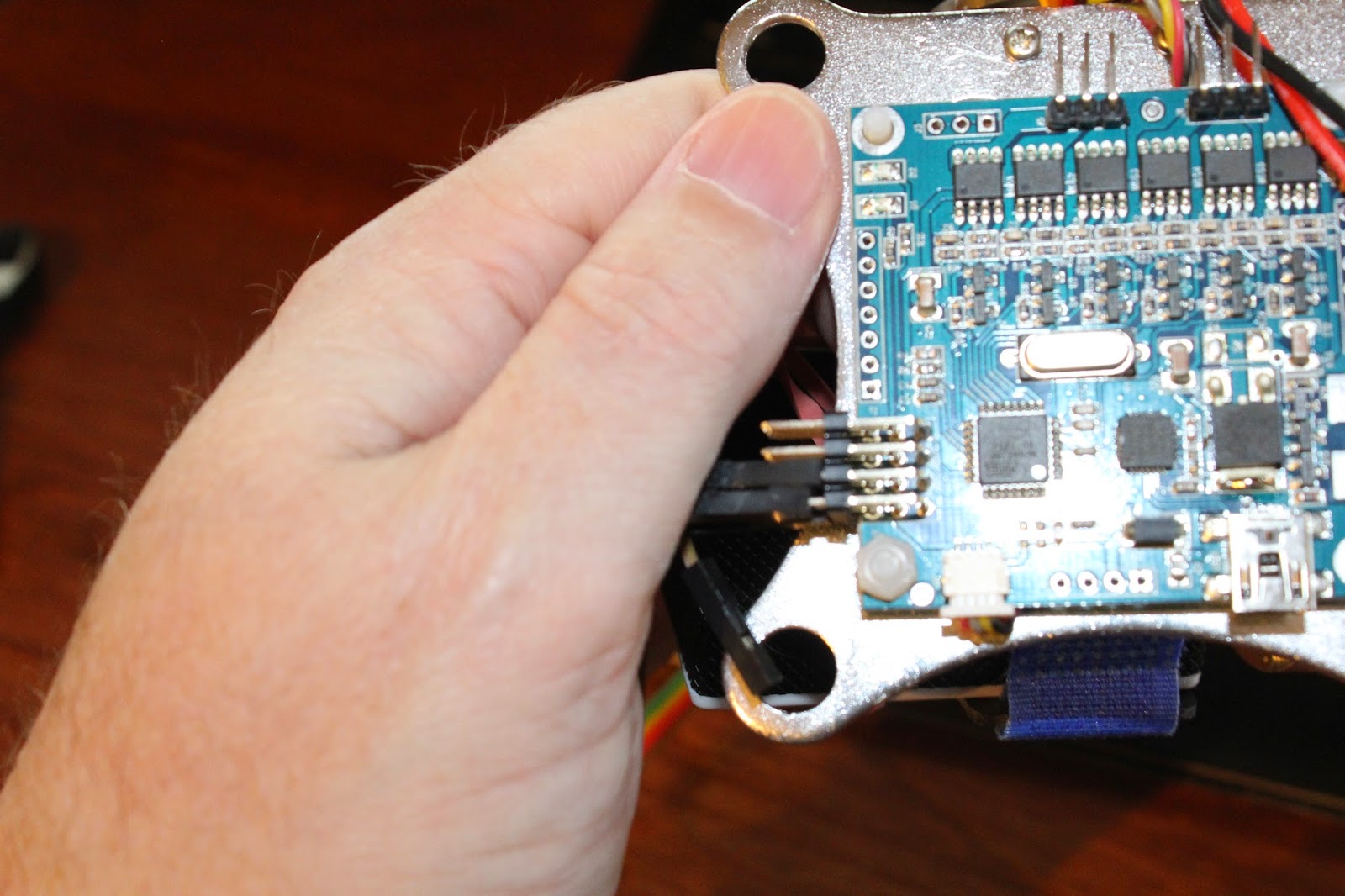
The external plug location.

First off. Since most of us add a camera and gimbal to quads over 250mm, One of the problems we all run into on the CX20 is the location of the electrical connection on the belly. a slight modification opens up your options a lot.

When you have it together, carefully analyze where would work for you. Take pictures and pencil in some ideas. Then open it up and lets get to work.


Again, don't do ANY cuts until you have it open so you don't cut any wires.

The plugs would have been sticking out if I attached the mini circuit board directly to the inside of the shell. so some 1/4" standoff blocks glued to the board and backed up with a single screw each. predrill to make it easier and prevent splitting.


The screws from inside that held the circuit board in place can be used on outside to hold it again (predrilled holes again. Make sure the board is centres so you can make all connections to the pins)

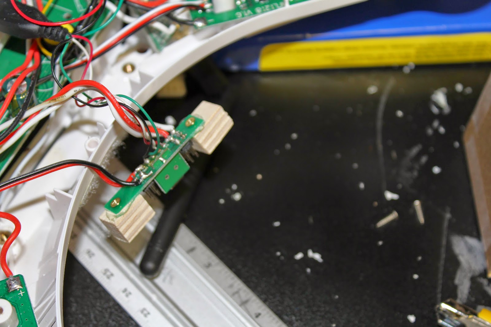
 Now that the connections are relocated. The old hole in the belly, I glued a small bit of styrene plastic over the open hole in the belly to put some strength back (not shown in this picture)


Accessory sideboards

I was never happy with the FPV transmitter velcro attachment on the side
There are all sorts of options you can order. Some even made of carbon fibre. These can be great, but can be expensive and you have to use extra precautions working with it.

I decided to proceed with this project. It also lets me show you a few interesting tidbits that might be unknown to some of you that I learned in my days of Fixed wing R/C aircraft.


First off, I looked at the structure of the CX20. It is a plastic shell design, Think of it like an exoskeleton. They entire structure comes from the the shape and curves of the body. If you take a sheet of thin cardboard, it's very flexible. No rigidity. Now if you bend it twice and tape it together, it is a triangular tube. now it is surprisingly strong. Some parts are in compression (squeezing) and some in tension (pulling apart, like pulling on rope). The other stress is shear (This is sort of like tearing). This is one of the basic principals of engineering. Using the right materials to be in tension and which in compression mean that you can combine several materials and the result can be stronger than either. Bear in mind that a substance can be hard but not strong, a substance can flex but be very strong.


The lightweight hobby grade plywood is great in compression and to some extent tension, and fair in shear strength but if you take a good general purpose aliphatic resin (wood glue or Weldbond) and use it to bind a single layer of fibreglass cloth to that plywood, the strength is amazing, It is strong in tension and compression and in shear.


What I did here was to take some Weldbond glue and water it down 2 parts glue, 1 part water. This lets it penetrate better into the cloth and the wood. It's probably not necessary but i do like the results.
I put a sheet of cellophane down, then the wood (1/8" birch plywood), apply a layer of the glue to the wood and lay the cloth on it. Make sure the cloth extends past the wood a few CM (less chance of the cloth falling apart). Work the cloth with some scrap cardboard until the glue is covering and coming through the entire area. Flip it over and repeat to create a double sided laminate. Cover this side with cellophane as well (To smooth and contain any oozing). I put this on a few sheets of newsprint (both sides, again to contain any oozing). place this on a clean smooth surface and place another clean smooth surface on top. Add weight then let this dry for 2 days. After the 2 days, it will not be fully cured yet. take it out, carefully remove the cellophane and let it continue to dry for another full day. Cut away the excess cloth that is not supported by wood and you have an amazingly strong homemade cheap composite panel. I cut of a strip about 2 CM wide of this composite and a similar sized bit of the 1/8" birch plywood without the glass cloth, then challenged a friend to break them, the bare plywood broke with only slight effort, The glass reinforced one he too 2 tries and notable effort to break it, but it still was in one part, just lost most of it's structure.
This finished composite cuts with little more effort than it did before so it is very workable, it's very light and very strong.
I'll grant that its not as strong as as carbon fibre panels, but it is still quite sufficient for many of our needs in this hobby.
  
 The stock thumbscrews from the landing gear easily allow you to use them through these accessory plates.


 I cut a large section out to allow access to the plugins
 The FPV transmitter sits more securely with velcro holding it in place. A rubber band is cheap backup.


Extending the CX20 Battery Bay

I have purchased a 3200Mah Lipo for my CX20, and the battery bay is too short to fit it. After a bit of basic design work and examining the structure, I had a plan....

I opened the shell of the CX20 and made sure there were no wires in any peril. Measuring the battery and all the plastic several times over,


I took a Dremel and cut into the belly just where the front curves up. I cut the sides just where there are 2 vertical plastic stiffeners. I left the narrow strip at the top (about 4 MM) intact since it provides structure in tension. It wasn't much but it would have sagged otherwise (I am over 50, trust me, I know about sagging, lol).


Now to refine the sizing.


And work out the shape of the extension.


Since I was doing some body work anyway, I decided to install the FPV camera in this housing. And while I was doing this. Install a headlight. More on this at the end of the article.

A test part made of cardboard and tape lets me refine the shape and the fit before I cut the actual materials.

Speaking of which. I picked up some 40 thou (.040") Styrene plastic sheet at the plastics dealer. It's a little soft on it's own. I Glued some balsa to the back of the plastic. I used Gorilla Glue. I put a little plastic glue on the styrene and the gorilla glue on the balsa. Use some cellophane to contain the mess, and place this between two boards with some weight overnight.


...unfortunately they slid a bit.
Note to self, a strip of tape would reduce the chances of this.

 trimmed off the excess balsa, then did one final fitting with some more cardboard.


With that final set of shapes, I cut the bottom and side panels of the box.


The front plate is easy to work out at this point. I carefully ground out the hole to fit the LED diffuser and the camera. The flipped open top was for figuring out how it was going to be finished.


I was going to build the cover from strips built up. but the thing was not working out.


Using a few bits of thicker balsa, I was able to build a different cap and shape it to mate with the upper shell. I glued in a strip of 1/8" ply for a screw point and a block in the bottom half for the screw to attach to.

A little foam as a means of keeping the battery from moving around worked well.
The 3200Mah battery fits in with ease. It fits like a dream. The 5500mah battery is just a little too thick to fit in the extension. I could have made it a little bigger but this was done before the 5500's showed up.

The point of this extension is to house the larger batteries with the door closed, and to house the FPV camera and the LED headlight.


Now the headlight..... I ordered some high intensity LED headlights from Banggood.

http://www.banggood.com/Stunning-Highlight-LED-Night-Light-for-Multicopter-p-917959.html

They are cheap and intense, remember that they need 3V, not 5V.

Some are to be fixed and work with the FPV camera as well as help with orientation and navigation.

My further plan is to put 2 on the Gimbaled camera too (so that they can tilt and pitch with the camera.


......Now most of you have access to a Costco. Look for a 3 pack of headlights like this.


These are a perfect source of a similar LED that runs off of 5V.

I find it funny that you have to open the back to see the instructions telling you that you can open the back.
3 screws in the battery compartment will let you open it up.


The little circuit board contains a switch and a tiny chip. You can't really use it, BUT if you can, you can desolder the surface mounted resistor and wiring it inline with the LED. alternately get yourself a ballast resistor and wire it in series. I have a 5V BEC rigged inside and hotglued in the LED and it's diffuser. It puts out light like a huge amount of light in a tight beam. For FPV when you are looking in shadows, it's quite handy.


Monday, March 16, 2015

Camera gimbal redux

Now that we have tested the gimbal on our test quad, we redid the whole mounting system. There is a bit of  'Red Green' to the method but it works and it's not ugly, Plus we gained the clearance to remove those landing leg extensions.Although I am still not happy with where the sensors for the gimbal are.

Before:
 After:

 Here is how we did it:

As you may recall, the mounts the gimbal comes with are designed to bolt right onto the DJI Phantom series. The difference in body design mean that the mounting plae is far too wide to use directly on the CX20. there are some ways to do some major cutting and grinding to fit it. This still would have also blocked access to the plug ports on the bottom. Our first 'quick and dirty' installation was fast but had a lot of it's own compromises. Including extending the height of the landing skids.


The CX20 mounting plates are far narrower and while good for clearance, it is not wide enough to allow the gimbal controller board to mount in the same manner.


to move everything forward and keep an unobstructed camera viewing angle, clear of the landing legs, the arms and the props, We wanted to keep the same forward mounted position. so we will be using the rear pair of mounting holes.


The gimbal mount uses larger grommets so they will have to be drilled out, and the gimbal used 2 machine screws that need to be drilled. the mounting holes are ever so slightly too small so a quick drill out on them is important too.

                    Grommet holes = 8.25mm (21/64")
                    Gimbal screw mount holes = 2mm (7/64")
                    Note: use the same 2mm to 'chase' out the stock screw holes near the 2 you just drilled. 

Make sure you clean up the sharp edges after drilling or the grommets will have a very short life.


I hope you marked the wires and mounting position of everything.


Attach the grommets in the rear holes of the upper plate and i like to also insert a zip tie loosely through the grommet as insurance. Double sized tape on the front of the belly to help keep things sturdy. If I was planning on opening up the belly of the beast, I would put a bolt through from the inside.


I attached the control board under the lower plate, just some double sided tape. I tried to use a minimal amount. Securing the board from vibration and from rubbing the metal plates is important, and not preventing any of the small electronic parts for getting the cooling air it likes is the trick.


 2 small zip ties keep it from going astray.
...backup support from a long zip tie around the board and the plate never hurts.

Making sure that the rear two grommets are already mounted will make the task of attaching a little less frustrating, but it is a challenge no matter what.

very loosely start the zip tie that goes through the grommet. DO NOT TIGHTEN !!!! or you will remove the whole point of the antivibration grommets. The whole reason for these is in case a grommet fails, you will still have your camera come home with the drone.


And here we have the completed installation, a bit lighter (not a lot) and no need for the extension of the landing gear (more weight and bulk saved).


I strongly suggest some protective wrapping of the gimbal sensors (the tiny circuit board under the gimbal just to the right of the blue velcro strap) this is a quite vulnerable position. I would have preferred that the gimbal bracket camera holder be above and the sensor there instead.


Results:
Ok, looks wise and clearance wise you can see for yourself.
Performance wise: a notable difference. I will have to retest with the flights times, but it react much nicer and seems a lot less encumbered. I would say it's somewhere in between the previous mount (heavily encumbered) and the basic fixed mount (moderately encumbered). it was certainly not the spritely CX20 that we all know and love, but it has some of it's 'oomph' back.
To the point where stripping this thing off is no longer something I 'HAVE TO DO'.
  
.....Now as to the performance: You may recall the last batch of figures, I will repeat and tell you that this helped a LOT!

2700Mah stock battery: 
Clean: 15 minutes
Fixed Camera: 12 minutes
Gimbal & Camera: 7 minutes.
Redone gimbal: 9:05  minutes

3200Mah Battery:
Clean: 17 minutes
Fixed Camera:
14:15
Gimbal & Camera: 10 minutes.
Redone gimbal: 10:55 minutes


That is a 2 minute gain !

Now as to the performance and handling:

Clean: Very responsive. quite nimble. less than half throttle and it's still climbing.
Fixed Camera: a slight bit less sporty but still very active. about half throttle to climb
Gimbal & Camera: noticeably more sedate. Much less responsive. 60%+ throttle to hover.
Redone gimbal: Performance although obviously feeling encumbered, is not feeling like it is near it's limit. a lot of the handling has returned so some extent.

Additional Note:
One observation I have is that the SJ4000 camera uses a micro USB connection instad of a Mini USB like the GoPro cameras do. The location of the camera on the gimbal make it difficult to connect this camera for live video feed or FPV without a big of fiddling around. Had the USB connector been on the other side of the camera, or the pitch motor been on the other side, things would have been a lot simpler.